Node impedance simulation
[ Home ] [ Design WorkBook ] [ Back ]
Contents
- Introduction
- Procedure
- Simulation example
Keywords:
Introduction
Procedure
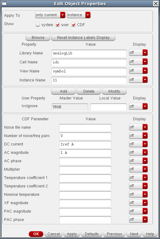
Basta attaccare un idc source al nodo di cui si vuole misurare l'impedenza di uscita e mettere AC=1. Poi analisi in frequenza e la tensione in Volt che mi esce e' anche il valore della resistenza in ohm (essendo R = V/I con I=1A)
apply a test current Iout and watch the effect on the output voltage (or vice versa).
Since Zout = Vout/Iout and Iout (ac) == 1, the magnitude of the output voltage corresponds indeed with the output impedance of your circuit.
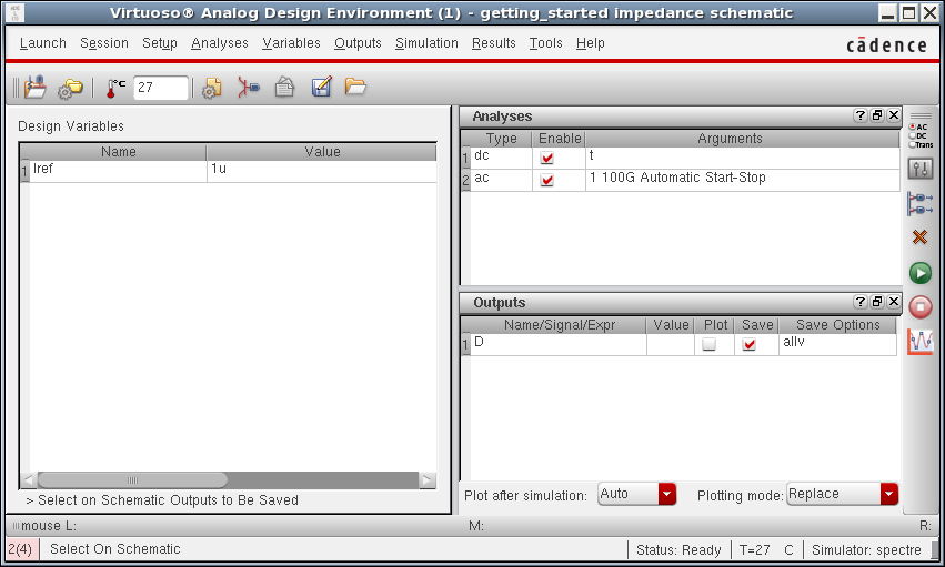
In general you have to ensure that your device has the correct DC bias. The output resistance given by AC analysis is dependent on the bias. In general, you add a DC source (if needed for biasing) and then perform an AC analysis to get output impedance.
Place this source across the nodes where you want to measure the impedance. The Value attribute of the Current Source should be defined as 'AC 1'. This provides a 1A AC current source for AC analysis. Enter AC analysis.
Since the current is 1A, the voltage across the current source is equivalent to the impedance, so this expression will produce the impedance plot.
Simulation example
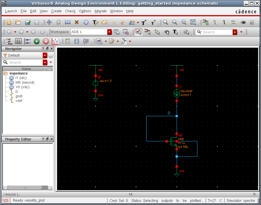
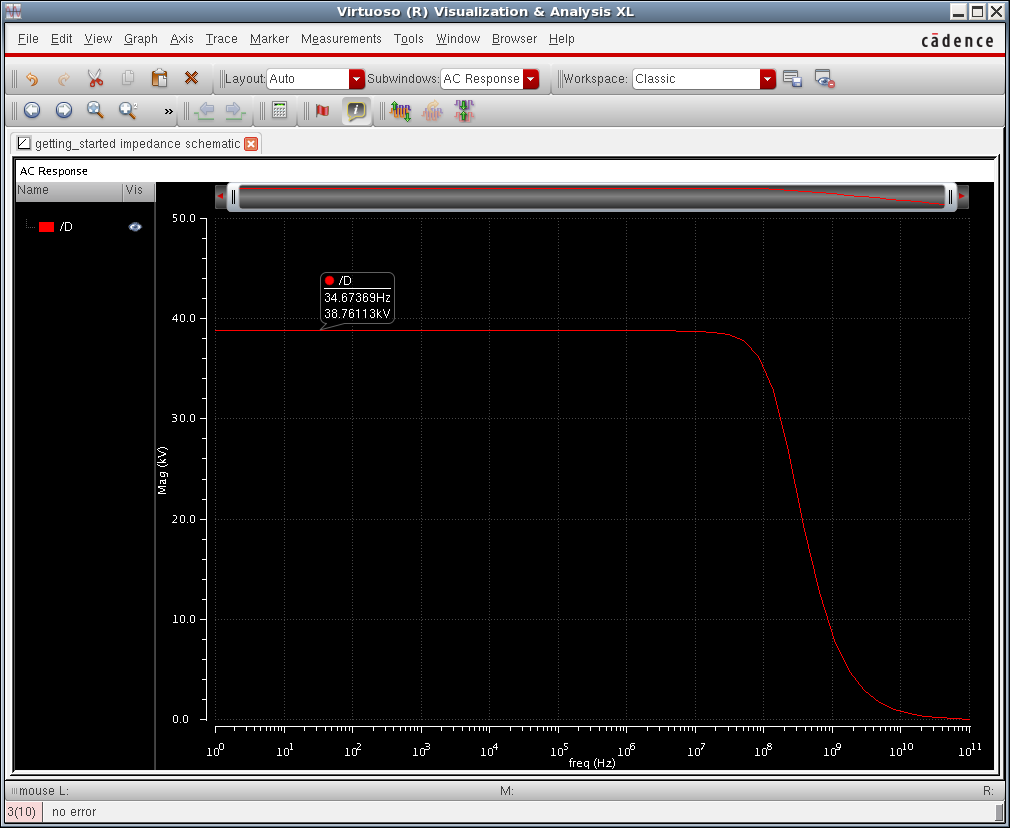
Esempio: diode connected NMOS
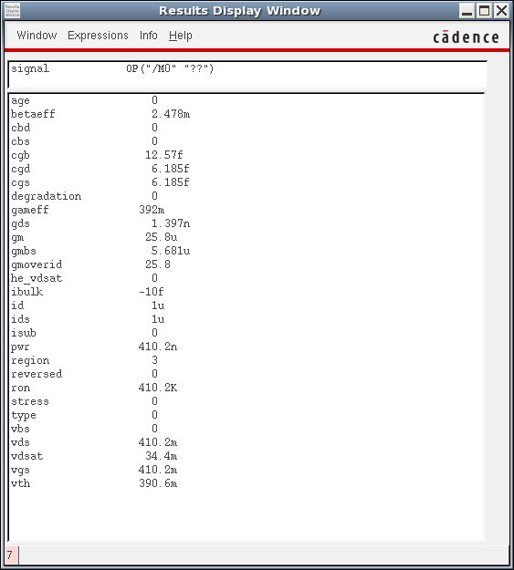
gm = 25.8 uS, gds << gm
1/gm = 38.76 kohm
Vg = 38.76 kV poi su 1 A sono proprio 38.76 kΩ
