Symbol creation tutorial
Schematic entry
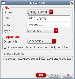
Creare una nuova cella ideal_opamp CIW ⇒ File ⇒ New ⇒ Cell View…
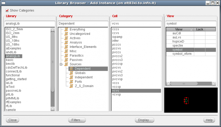
Istanziare vcvs,
analogLib ⇒ Show Categories ⇒ Sources ⇒ Dependent ⇒ vcvs ⇒ symbol
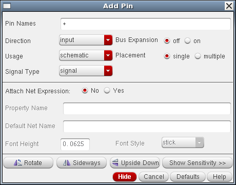
Istanziare i pins:
Schematic L ⇒ Create ⇒ Pin <P>
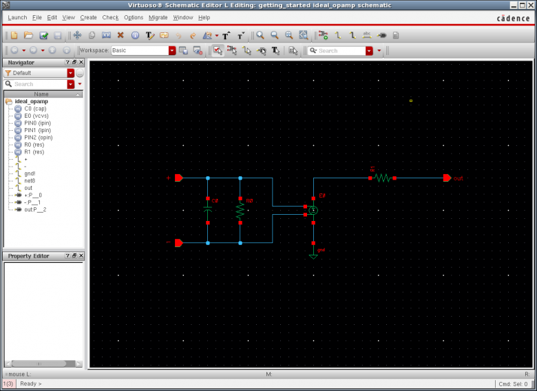
Aggiungere Rin, Rout e Cin che limita la banda bassante.
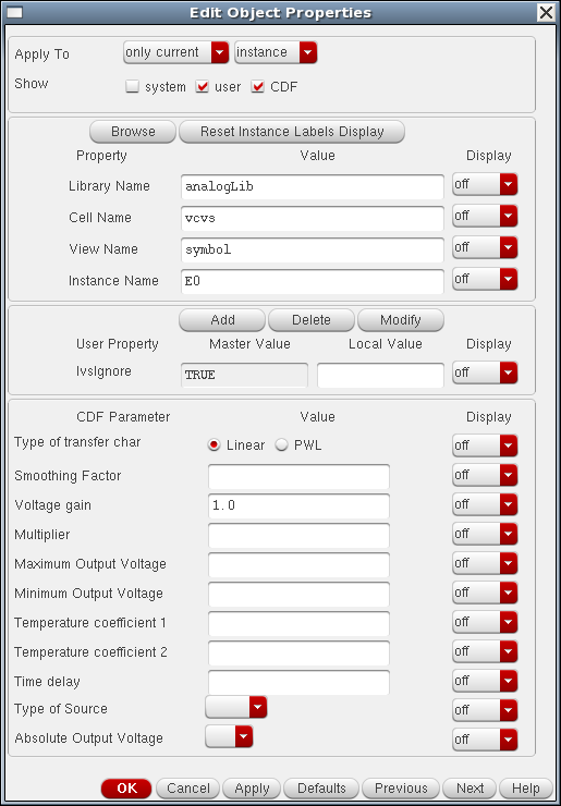
Infine editare le properties dei componenti, e.g. select the vcvs instance, then left click Editi ⇒ Properties ⇒ Objects… or simply press Q
Assegnare ad esempio gain = 10M max + 2.5 min = -2.5 delay = 0
Rin = 10G Cin = 1f Rout = 100
Alla fine Check and Save
Generate symbol from the schematic
As already mentioned there are two different ways you can create a symbol:
- create a new symbol cell view from scratch using the Library Manager
- automatically generate a symbol cell view from your schematic
Since the second way is much faster here we describe the automatic procedure.
At this point you should be in front of your opamp_ideal schematic cell view in the
Virtuoso Schematic Editor L window. If not open it from the Library Manager. To automatically
generate a symbol cell view for your ideal OPAMP left click
Schematic Editor L ⇒ Create ⇒ Cell view ⇒ From cell view
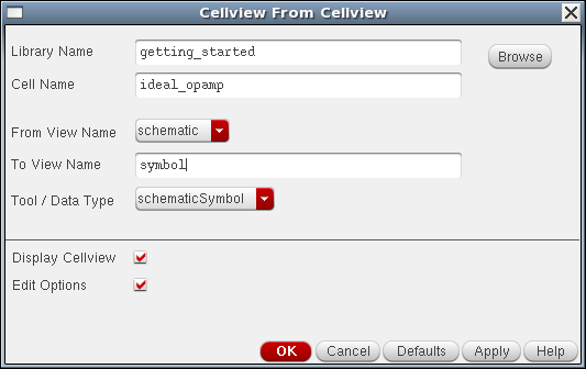
The Cellview From Cellview window should appear as shown below. This window allows a symbol to be automatically generated from the schematic view. Check that Library Name and Cell Name correspond to the OPAMP design and left click OK.
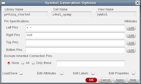
Next the Symbol Generation Options window will appear. In this window you can find the list of all pins
used in your schematic. Cadence has already identified the input pins + and - and the output pin
out and has already added input pins as left pins and the output pin as right pin. Left click OK.
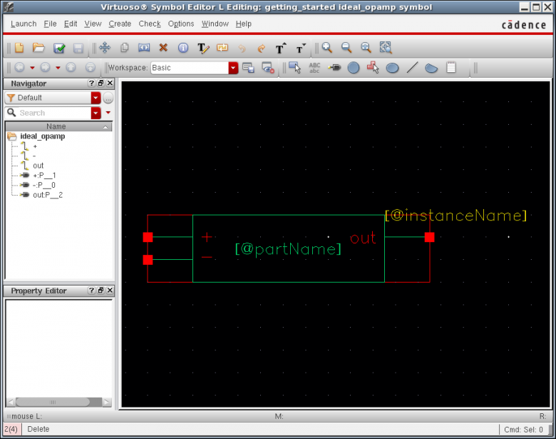
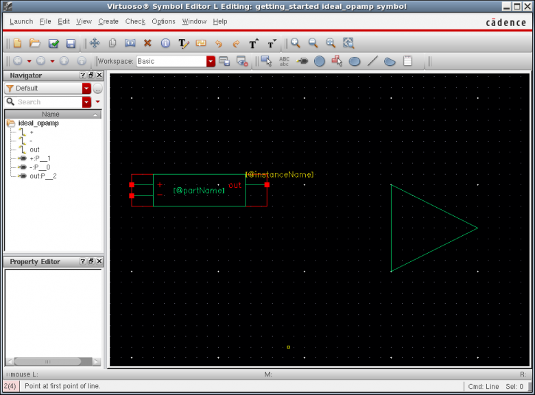
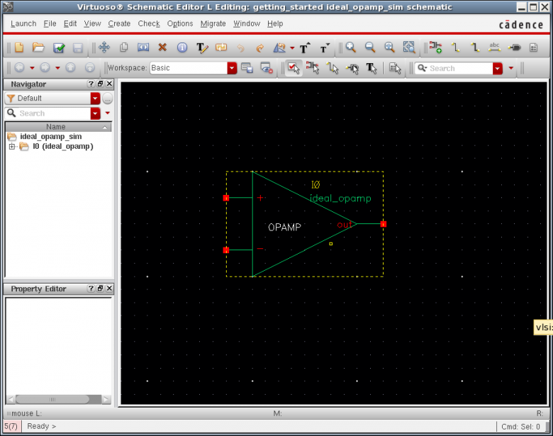
The Virtuoso Symbol Editor L window appear and Cadence has now already generated a default symbol for you
using pin specifications previously given. You can now use this default symbol as a starting point to create a full-custom
OPAMP symbol.
For detailed information about symbol creation in Cadence left click Help ⇒ Contents in Virtuoso Symbol Editor L
and go through Chapter 5 Creating Symbols of the Virtuoso L Schematic Editor User Guide. If you prefere open the symbolic link comhelp.pdf placed in your ~/cadence/doc/IC_6.1.5 directory (see also to the Cadence documentation wiki page ).
Cadence generated a default green rectangle with + and - input pins and out outpu pin. Moreover labels [@instanceName] and [@partName] have been automatically created. Note that the whole symbol is drawn inside
a red rectangle.
- green lines represent shapes
- the external red rectangle is the selection box
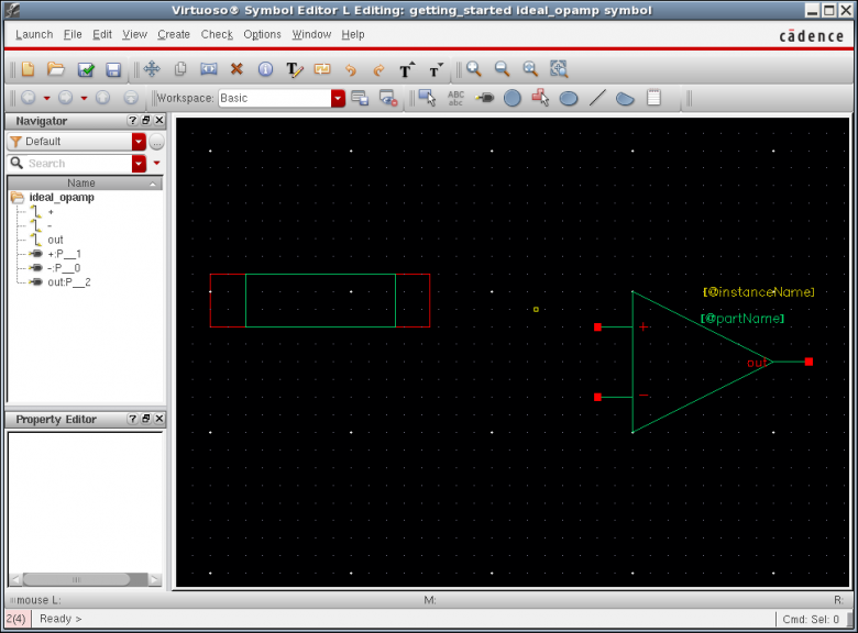
Importante: red rectangle rappresenta l'area complessiva del simbolo selection box, quella che poi si illumina quando seleziono un'istanza del simbolo
green lines sono solo design lines, posso usare linee, creare shapes/circles etc.
Create ⇒ Shape ⇒ Line
Click allo start, poi grag the mouse, click di nuovo per cambiare direzione, doppio click sul punto di arrivo per terminare
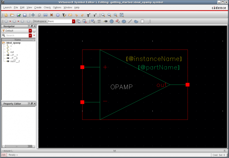
Conviene prima disegnare la forma desiderata, poi spostare i pin e il rettangolo rosso e poi delete the default green rectangle
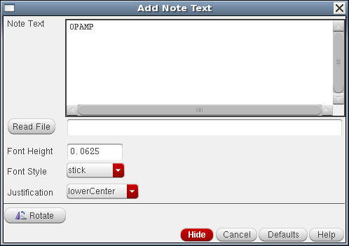
You can add a text label with Create ⇒ Note ⇒ Test (Shift + N)
It is a good practice to document a schematic or a symbol.
→ NLP label (cioe' quando istanzio diventa I0, I1, I2 ….
[@partName]
the system displays the NLP label [@instanceName] in the symbol window but displays a value–for example, I3–in the schematic window
Check and Save the design and Exit the Symbol Editor
Testbech schematic
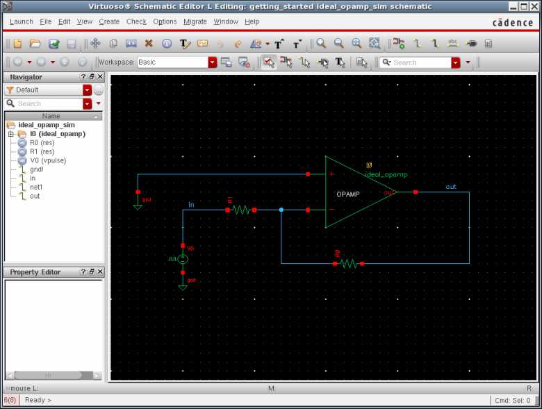
Creare una nuova cell _sim e.g opamp_ideal_sim to test the symbol behavior
E poi istanziare the symbol view of the opamp_ideal cell previously created!
Se voglio discendere nella design hierarchy uso
Schematic L ⇒ Edit ⇒ Hierarchy ⇒ Descend Edit… (e)
Schematic L ⇒ Edit ⇒ Hierarchy ⇒ Return (Ctrl + e)
Simulare e.g. un amplificatore invertente:
Quindi uso un vpulse e faccio un'analisi in transitorio e verifico il guadagno:
Attenzione all'escursione pero'!!!!!!!!! Se metto min=0 allora il common mode voltage non deve essere il ground! ma devo shiftare tutto a ~1/2 dinamica!! Altrimenti ho clipping del segnale!
Quindi: Vmax = Vdd Vmin=0 allora
Fare anche un'analisi AC cosi' da vedere la limitazione di banda passante introdotta da Cin finita
